Back to radio overview
Posted on: 9 March 2024

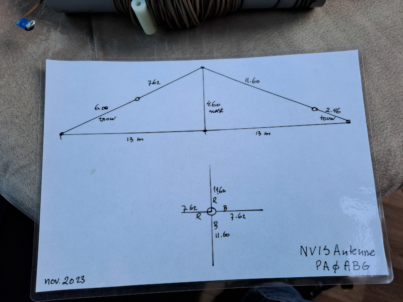
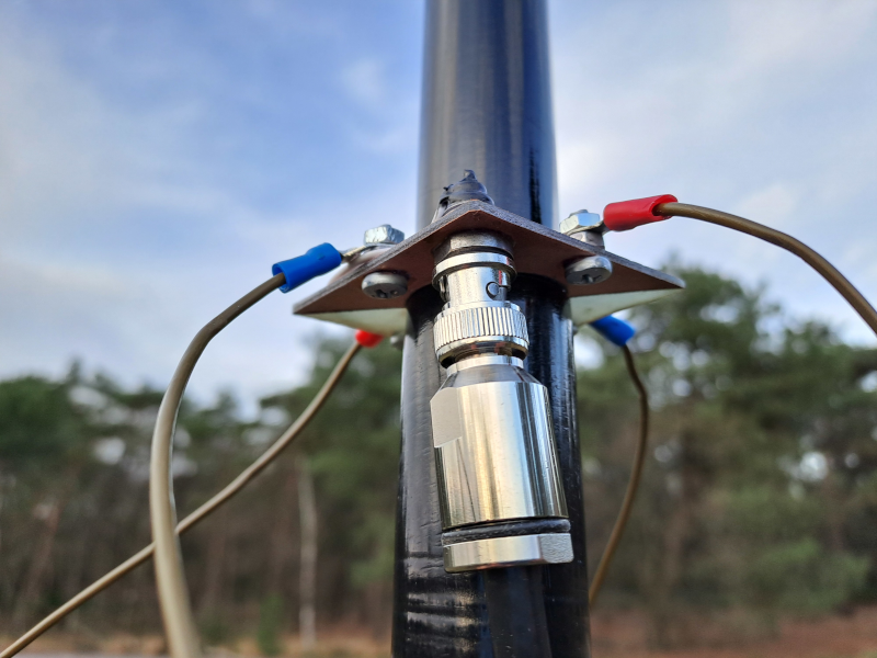
This Near vertical incidence skywave antenna was made for me by PA0ABG.

N V I S setup diagram
NVIS setup diagram

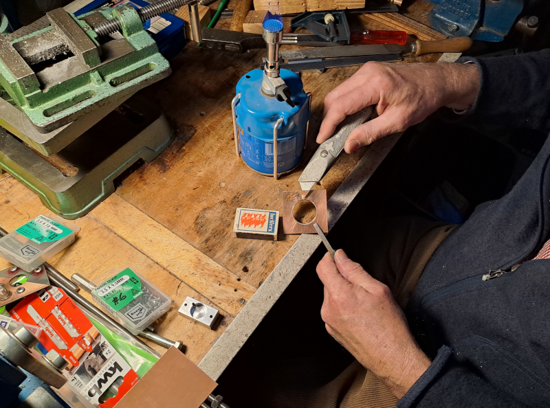
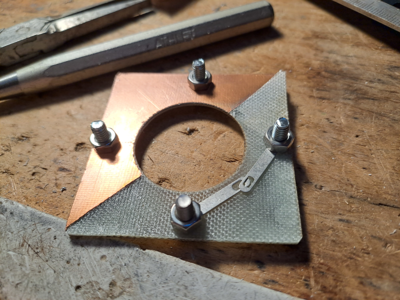
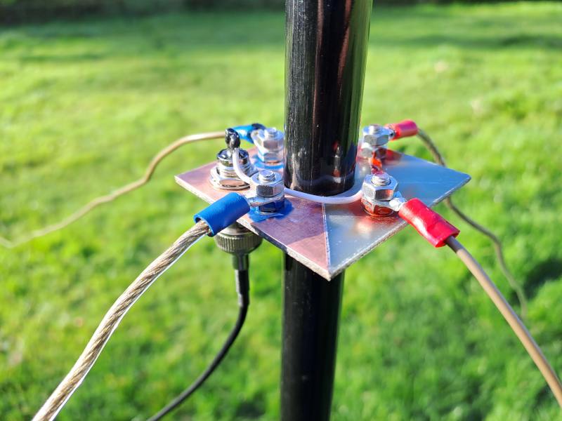
A FR-4 PCB is used. Half of it was scraped off for this design.

N V I S P C B scrape
NVIS PCB scrape
N V I S P C B
NVIS PCB
N V I S P C B liquid tape
NVIS PCB liquid tape
N V I S coax connector
NVIS coax connector
N V I S P C B
NVIS PCB

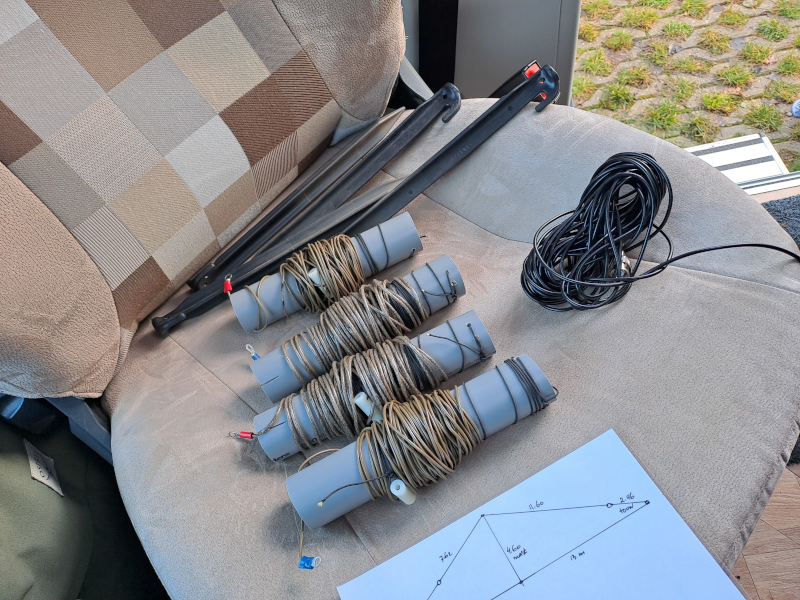
The antenne wires, coiled on a piece of pipe.
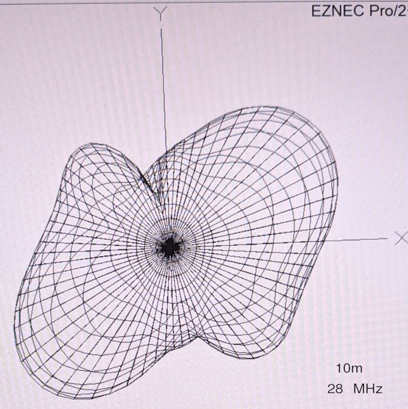
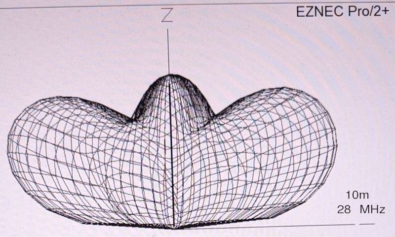
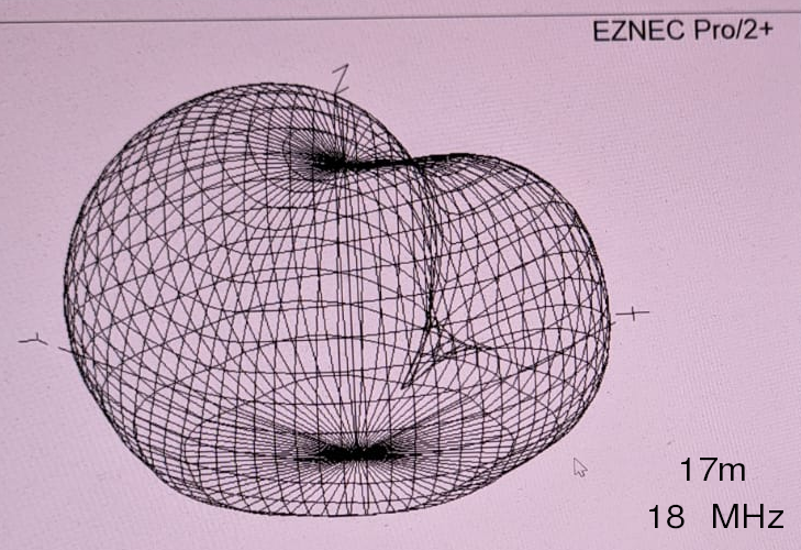
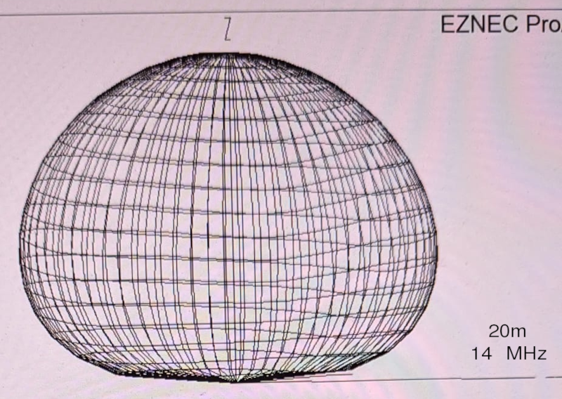
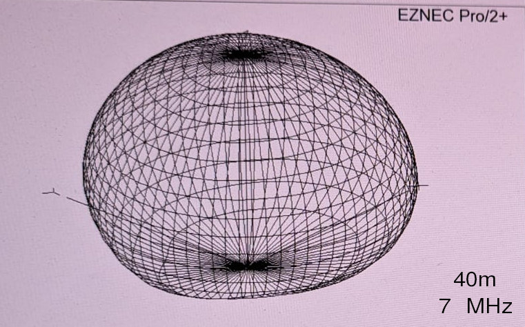
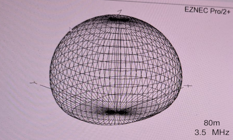
N V I S wire coils
NVIS wire coils

Diagrams

Some 3d plots of this antenna on 10, 17, 20, 40 and 80 meters made with EZNEC software by PA0ABG. The antenna is most effective on 20, 40 and 80 meters, where the waves go upwards.

N V I S 10 meter 28 mega hertz diagram top
NVIS 10 meter 28 mega hertz diagram top
N V I S 10 meter 28 mega hertz diagram side
NVIS 10 meter 28 mega hertz diagram side
N V I S 17 meter 18 mega hertz diagram
NVIS 17 meter 18 mega hertz diagram
N V I S 20 meter 14 mega hertz diagram
NVIS 20 meter 14 mega hertz diagram
N V I S 20 meter 14 mega hertz diagram
NVIS 20 meter 14 mega hertz diagram
N V I S 40 meter 7 mega hertz diagram
NVIS 40 meter 7 mega hertz diagram
N V I S 80 meter 3.5 mega hertz diagram
NVIS 80 meter 3.5 mega hertz diagram

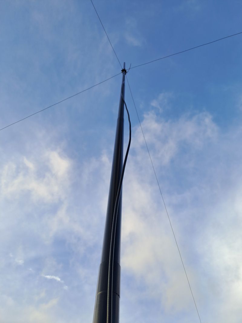
The antenna deployed in the field.

N V I S antenna
NVIS antenna

Back to radio overview